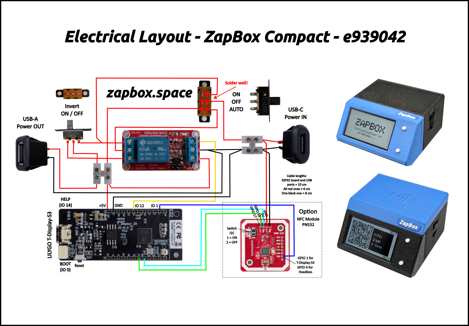
Use with LILYGO T-Display-S3. Headless version see here.
Note: The configuration data can be deleted using "Erase device." Otherwise, it will be retained even with the new firmware. LOGS & CONSOLE is no needed.
When you flash a new ESP32 or use “Erase device.” the ZapBox automatically starts in configuration mode and displays the following message: “CONF / SERIAL CONFIG MODE.”
→ The ZapBox is now ready to receive configuration data. ⚙️
If parameters have already been stored and need to be changed, you can also open CONF mode retrospectively:
Note: The connection will remain active for 3 minutes (180 seconds) before it is automatically disconnected. If data is already available. You can terminate the connection prematurely by pressing the NEXT button, touching the display, or pressing the external button.
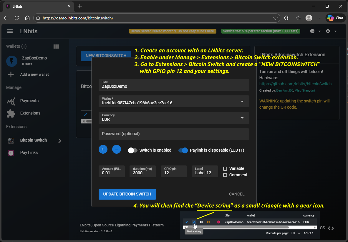
How do I get the device string? Use Bitcoin Switch or ZapBox extension → Help
Note: The default is Bech32. LUD-17 is easier to scan, but is not yet supported by all types of wallets.
Note: The LED button YES function hides the texts HELP and NEXT on the display.
Function of the LED button - press:
• once => Change display / product
• once and hold => Help page
• several times => Report page
• once briefly and then hold at least 5 seconds => CONF page
ZapBox Mode: Activate up to 4 GPIO pins (12, 13, 10, 11) with unique QR codes. Product labels and LNURLs are automatically retrieved from your LNbits switch configuration. Use NEXT button, touch gestures (swipe ←→) or external button (if available) to navigate between products. Servo mode requires additional settings. See below.
Note: The Threshold function is compatible with the default Compact (1 channel) mode and with Servo mode when using "One for All" activation option.
-> To enable the servo configuration, please select the ZapBox Mode - Servo
Servo Configuration
Up to 4 channels can be controlled.
Pin 12: Relay (on/off, standard)
Pin 13: Configurable (off/relay/180° servo/360° servo)
Pin 10: Configurable (off/relay/180° servo/360° servo)
Pin 11: Relay (on/off, also usable for ambient lighting)
The "One for All" function allows all channels to be triggered simultaneously. To do this, you only need to configure pin 12 and, if necessary, a servo. In addition, the channels can also be configured and activated individually. To do this, the pins must be configured in LNbits and the servos must be set up.
The servos are activated by setting a parameter value ≠ 0.
Note on One-for-All Mode: If only GPIO pin 12 is configured in LNbits, all other outputs will switch using the same timing. However, once a GPIO pin (13, 10, or 11) has its own configuration entry and therefore its own timing, this timing will be used for that pin independently of how pin 12 is switched.
Select the function for GPIO Pin 13
Select the function for GPIO Pin 10
Servos become active when their values are non-zero. "Relay function (external relay)" uses Pin 13/10 as a standard relay output — an external relay module must be connected. Special Mode (blink, pulse, etc.) works for relays (Pin 12/11) and relay-function pins (Pin 13/10), but not for servo pins.
NPN input on Pin 2 (light barrier / limit switch)
Pin 11 is always ON, except in screensaver mode.
Notes:
Stop the advance: A trigger from e.g. a light barrier (NPN) stops the action after 2 seconds at the earliest.
Monitoring product blockage: The (NPN) input (light barrier/limit switch) displays the message "PRODUCT IN THE EJECTOR - Remove the product" and no further payment is possible until the input is free again.
Level monitoring: The (NPN) input monitors the fill level of a magazine or container. As long as Pin 2 is pulled LOW (sensor active), everything is fine. As soon as Pin 2 is HIGH (sensor free), all payment options are blocked and the message "THE SUPPLY BIN IS EMPTY - Please restock it" is displayed. Payments are re-enabled automatically once the sensor is active again.
Note on "Ambient lighting switch": With pre-selection enabled, channel 4 is switched depending on the display backlight. Whenever the display is on, channel 4 is activated, thus, for example, the lighting for a vending machine. If the display backlight switches off because the screensaver mode is active, channel 4 is also deactivated.
NPN input on Pin 3 (T-Display-S3 only) — controls / monitors Channel 1 (GPIO 12)
Stop / Monitoring / Level Monitoring: Same behavior as "Special features for the vending machine" but using GPIO 3 instead of GPIO 2. Triggers and blocks always refer to Channel 1 (GPIO 12).
FD (Field Detection): GPIO 3 is configured as input for the INT/FD pin of the NFC Tag 2 Click module. When a mobile phone approaches the NFC tag, the FD pin goes HIGH — the ZapBox logs the event. No relay action is triggered; this is for diagnostics and future extensions only.
Choose pulsing/blinking mode for relay control
Note: Special modes control how the relay switches during the configured duration. "Standard" means simple on/off. Other modes create pulsing/blinking patterns with configurable frequency and duty cycle.
Control when Bitcoin price/block info is shown
E.g. USD, EUR, GBP, JPY, CHF, TRY, CAD, BRL, CUP, etc.
OFF: No ticker shown (Duo/Quattro: productSelectionScreen; Single: only QR code)
ON - always: Ticker overlays screen, navigate with NEXT/swipe to show products temporarily (returns after timeout)
ON - when selecting: Single: Ticker only visible for a short time after NEXT/swipe. Duo/Quattro: productSelectionScreen → products → ticker (at end of product cycle)
leave empty for normal mode (default)
placeholder
12 (default)
Note: As soon as something is entered in the "Wallet Invoice/Read Key" field, "THRESHOLD MODE" becomes active. "NORMAL MODE" then no longer works. The data specified in the bitcoinSwitch extension, such as amount, PIN, and time, is ignored. Only a payment to the wallet with the invoice key counts.
How can I use this? Either by receiving payment directly into the wallet or by using the "Pay Links" extension. There you can get a static LNURL and even a lightning address. Payments to these addresses then trigger the pin, provided the threshold value is reached or exceeded.
1-120 minutes (default: 5)
1-120 minutes (default: 30)
Use Cases: Energy saving (screensaver ~80-90%, light sleep ~99%, freeze ~99.9%), reducing device heat, extending display lifespan in always-on scenarios.
⚡ Light sleep is recommended for devices with an external LED button. In freeze mode, only BOOT and HELP buttons can wake the device.
Note: T-Display-S3 with touch, only the screensaver mode can be used. The ESP32 cannot be reactivated via touch while in Deep Sleep mode.
The NFC Bolt Card functionality requires the LNbits extension "zapbox_extension". The ZapBox automatically detects which extension is installed on your server – no manual configuration required. If "zapbox_extension" is active, NFC Bolt Card payments are available out of the box. If only "bitcoinswitch_extension" (Bitcoin Switch) is installed, the ZapBox switches to that automatically.
Repositories from where the extensions can be downloaded:
https://installer.zapbox.space/extensions.json
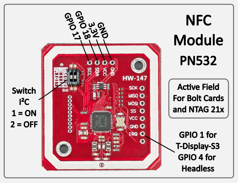
Bolt Cards & NTAG 21x (PN532, I²C 0x24) — Active NFC reader: the PN532 generates its own magnetic field and reads cards placed on it. Supports pre-programmed Bolt Cards for contactless Lightning payment. Also reads passive NFC tags of type NTAG 213, 215 and 216 — e.g. for LNURL-based payment tags. Works with all major Lightning wallets and PoS systems. No configuration required — the module is auto-detected on the I²C bus at startup.
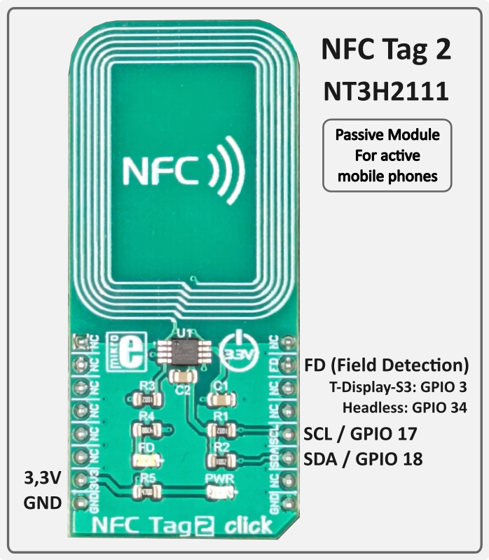
Mobile Phones (NFC Tag 2 / NT3H2111, I²C 0x55) — Passive NFC tag: unlike the PN532, the NT3H2111 generates no field of its own. It is a true NTAG chip that delivers the LNURL autonomously as soon as the active field of an approaching mobile phone is detected. The ZapBox writes the current LNURL to the chip via I²C — the ESP32 is not involved during the tap. Compatible with Android NFC Tools and wallets that support LNURL via NFC (e.g. Phoenix). No configuration required — auto-detected at startup.
Both modules operate independently and in parallel. If a module is not connected, it is simply skipped — normal operation is not affected.
PCF8574 on I2C (SDA=GPIO18, SCL=GPIO17) – address 0x20 (A0/A1/A2 all to GND)
The ZapBox features a hierarchical error detection system with automatic diagnostics. Errors are displayed on screen with abbreviations:
| Priority | Error Type | Abbreviation | Description |
|---|---|---|---|
| 1 (Highest) | NO WIFI | NW | WiFi network not connected → Wifi data correct? → WiFi signal too weak? |
| 2 | NO INTERNET | NI | Internet connectivity lost → Internet accessible? |
| 3 | NO SERVER | NS | LNbits server unreachable -> Server hardware down? -> Device string correct? |
| 4 (Lowest) | NO WEBSOCKET | NWS | WebSocket protocol/handshake failure -> LNbits down? -> Device string correct? |
Note: Higher priority errors override lower priority error displays. For example, if WiFi is down, all other checks are skipped and only "NO WIFI" is shown.
All errors with their occurrence counts (0-99) are logged on the Report page. To access the Report page:
If a wallet scanning the QR code shows an error message, here's what it means:
"bitcoinswitch ... is disabled" → The Bitcoin Switch was actively disabled in LNbits
"No active bitcoinswitch connections" → The handshake between the wallet and ZapBox failed. -> Wait or restart the ZapBox to re-establish the connection.
Relay does not switch, but payment was successful → Wrong GPIO pin configured in LNbits?
If you tap an NFC Bolt Card or NTAG21x tag and see "NFC not supported" on the display (shown for 5 seconds), and the serial log shows:
[WARN][NFC] Bolt Card tap detected – NFC is not supported by the active extension (bitcoinswitch).
[WARN][NFC] To use NFC / Bolt Cards, switch to zapbox_extension (apiPath = "zapbox").
This means the device is configured with the bitcoinswitch_extension, which does not have an NFC endpoint (/api/v1/nfc/). NFC payments are only supported by the zapbox_extension.
Solution:
This is not a hardware problem – the NFC reader works fine. It’s purely a server-side configuration issue.
{"detail":"LNURLW callback error: Payment failed - "}
The sending wallet and the receiving wallet in LNbits are the same. The Bolt Card wallet and the receiving wallet must be different wallets in LNbits.
Some ESP32s must first be put into mode before flashing or transferring data. Otherwise, they will refuse to transfer. Try these:
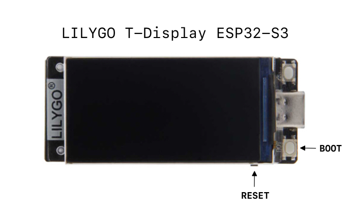
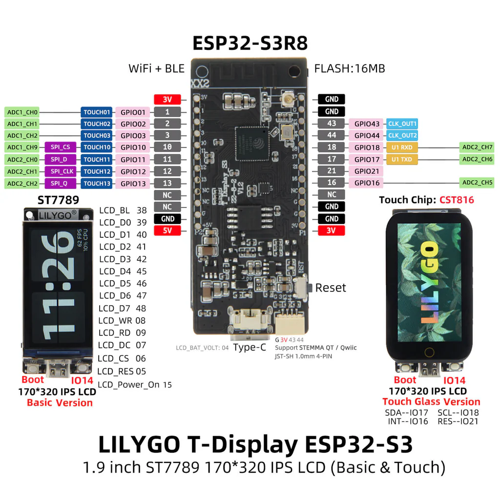
Source: lilygo.cc
Main page: https://zapbox.space
Web installer – T-Display-S3: https://installer.zapbox.space
Web installer – Headless (esp32dev): https://installer.zapbox.space/headless/
Further documentation: https://ereignishorizont.xyz/en/zapbox-en/
GitHub – ZapBox: https://github.com/AxelHamburch/ZapBox
GitHub – zapbox_extension: https://github.com/AxelHamburch/zapbox_extension
Extension manifest source: https://installer.zapbox.space/extensions.json
LNbits: https://lnbits.com/
GitHub – bitcoinswitch_extension: https://github.com/lnbits/bitcoinswitch_extension
bitcoinSwitch web installer: https://bitcoinswitch.lnbits.com/
MakerBits Telegram Gruppe: https://t.me/makerbits