Use with standard esp32. Version with Display see here.
Note: The configuration data can be deleted using "Erase device." Otherwise, it will be retained even with the new firmware. LOGS & CONSOLE is no needed.
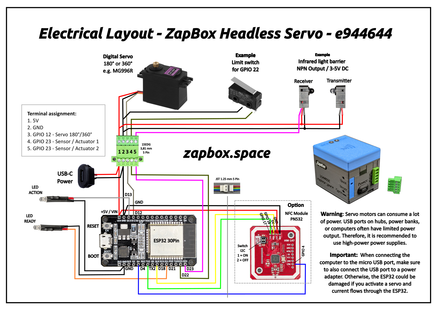
Note on the headless version: The headless version does not support display. The terminal window can be used for status monitoring and error analysis. LEDs connected to GPIO 21 and GPIO 2 (onboard LED) provide visual status feedback.
When you flash a new ESP32 or use “Erase device.” the ZapBox automatically starts in configuration mode and the ready LED will blink slow.”
→ The ZapBox is now ready to receive configuration data. ⚙️
If parameters have already been saved and need to be changed, you can also open CONF mode retrospectively by pressing and holding the BOOT button for at least 5 seconds.
Note: The connection will remain active for 3 minutes (180 seconds) before it is automatically disconnected. If data is already available. You can terminate the connection prematurely by pressing the BOOT button again.
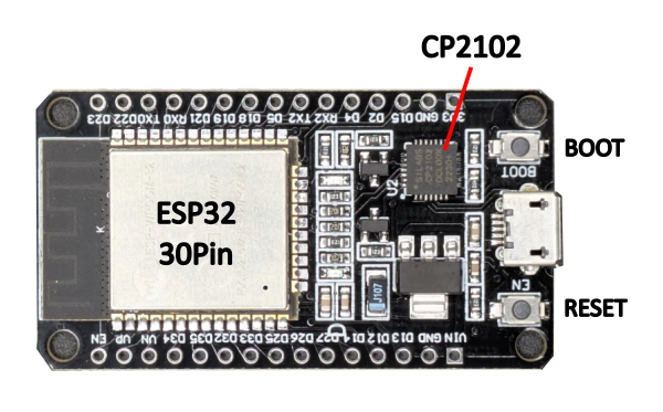
Note: Once you establish a connection by clicking “Connect” below, some ESP32s with special communication chips (CP2102) will restart once, and you will need to reactivate configuration mode after connecting.
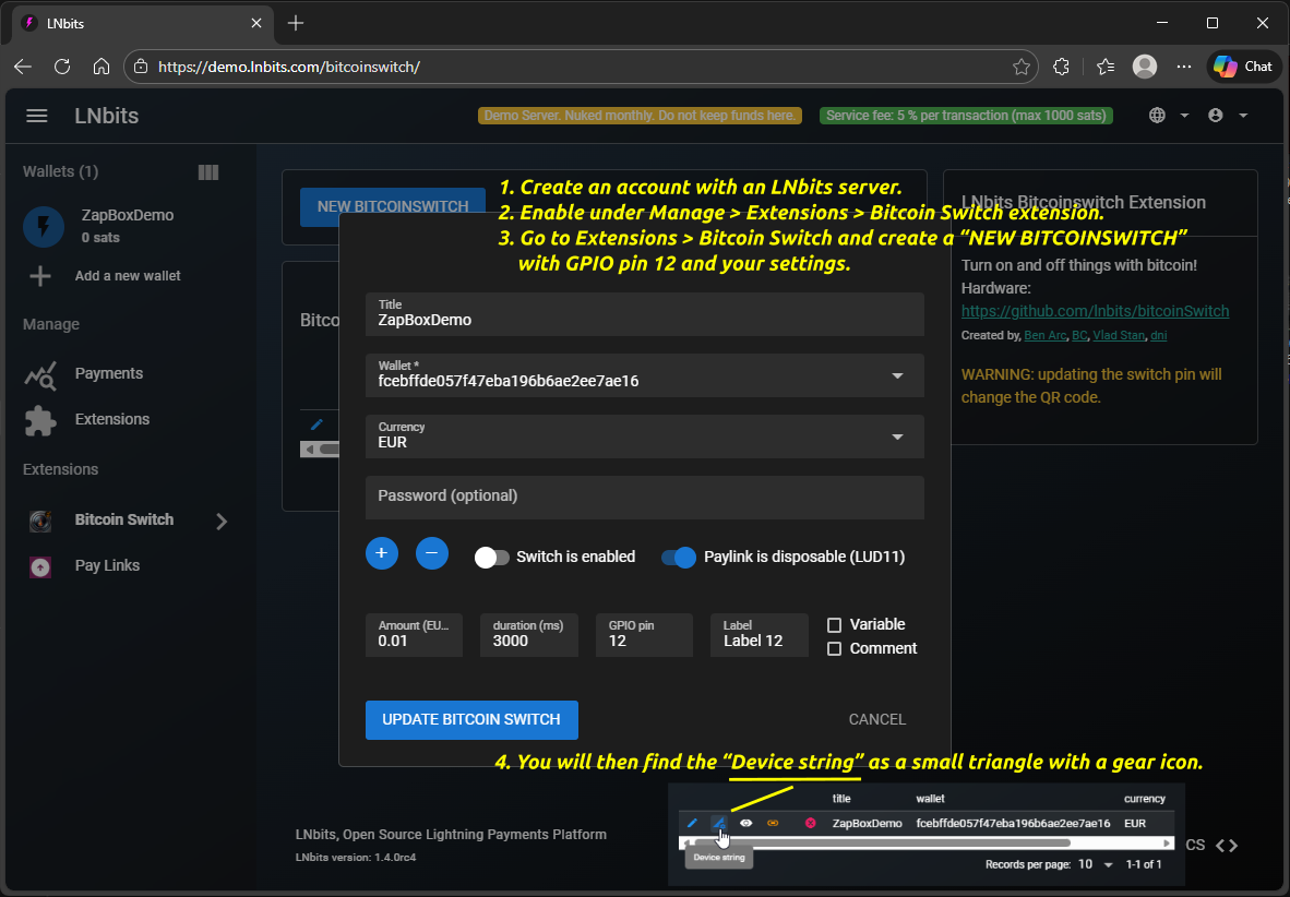
How do I get the device string? Use Bitcoin Switch or ZapBox extension → Help
Select the configuration for GPIO pin 12 / Connector terminal 3
Choose pulsing/blinking mode for relay control
Note: Special modes control how the relay switches during the configured duration. "Standard" means simple on/off. Other modes create pulsing/blinking patterns with configurable frequency and duty cycle.
Special features for vending machines
The headless ZapBox supports two independent sensor inputs for vending machine operation. Each sensor can be configured separately with one of four operating modes. Sensors use INPUT_PULLUP (active LOW — connect sensor signal to GND when triggered).
When a sensor blocks payments: The onboard LED blinks very fast (10 Hz), the WebSocket connection to the LNbits server is disconnected so the server rejects any static QR code payments, and NFC Bolt Card taps are blocked. As soon as the sensor condition clears, the WebSocket reconnects automatically and normal operation resumes.
Function for GPIO pin 22 / Connector terminal 4
Function for GPIO pin 23 / Connector terminal 5
Operating modes explained:
| Stop the advance | Stops the relay action when the sensor detects a product (LOW signal). Minimum action time of 2 seconds before the sensor can trigger. |
| Monitoring product blockage | After a payment, checks if the product exit is blocked (sensor LOW). Blocks further payments until the path is cleared. |
| Level monitoring | Continuously monitors the supply bin fill level. When the sensor goes HIGH (no product detected), the bin is considered empty and payments are blocked until restocked. |
| Relay output | External relays can be connected to GPIO 22 and 23. They will always switch together with GPIO 12, regardless of whether Relay or Servo function is selected. |
⚠ Important: When a sensor function is active on GPIO 22 or GPIO 23, those GPIOs are configured as INPUT_PULLUP and are no longer available as relay output channels (CH06/CH07). Make sure your LNbits switch configuration does not use these GPIOs when sensor features are active.
Multi-Channel Mode
The headless ZapBox supports up to 12 independent relay channels. Each channel maps to a GPIO output that can switch a relay, solenoid, or any other 3.3 V-driven load.
Available GPIO channels:
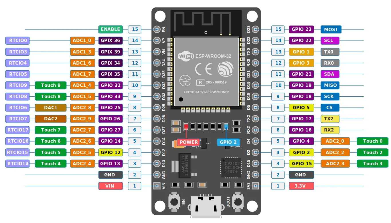
| CH01 | GPIO 12 | (default) |
| CH02 | GPIO 13 | (always switches together with GPIO 12 – LED indicator) |
| CH03 | GPIO 14 | |
| CH04 | GPIO 16 | |
| CH05 | GPIO 19 | |
| CH06 | GPIO 22 | (reserved when Sensor 1 is active) |
| CH07 | GPIO 23 | (reserved when Sensor 2 is active) |
| CH08 | GPIO 25 | |
| CH09 | GPIO 26 | |
| CH10 | GPIO 27 | |
| CH11 | GPIO 32 | |
| CH12 | GPIO 33 |
Each channel is configured independently in your LNbits extension (zapbox / bitcoinswitch) – each switch gets its own QR code and amount. The device activates exactly the GPIO returned in the "paid" event – all channels are ready at boot. No additional configuration on the device is needed.
Note on GPIO 13: GPIO 13 always switches together with GPIO 12 and can be used as a status LED to visually signal each activation. GPIOs 22 and 23 are reserved as relay outputs as long as no sensor function is configured on them.
leave empty for normal mode (default)
placeholder
12 (default)
Note: As soon as something is entered in the "Wallet Invoice/Read Key" field, "THRESHOLD MODE" becomes active. "NORMAL MODE" then no longer works. The data specified in the bitcoinSwitch extension, such as amount, PIN, and time, is ignored. Only a payment to the wallet with the invoice key counts.
How can I use this? Either by receiving payment directly into the wallet or by using the "Pay Links" extension. There you can get a static LNURL and even a lightning address. Payments to these addresses then trigger the pin, provided the threshold value is reached or exceeded.
NFC Bolt Cards work reliably and securely with all major Lightning wallets and PoS systems. This is the recommended default.
NFC card emulation (experimental): The ZapBox emulates an NFC tag so customers can pay by tapping their phone. Currently only supported by Phoenix Wallet, and even then, only with certain limitations. Other wallets may not even recognize the NFC tag. For best compatibility, use the QR code format "LNURL in LUD-17" instead.
The NFC Bolt Card functionality requires the LNbits extension "zapbox_extension". The ZapBox automatically detects which extension is installed on your server – no manual configuration required. If "zapbox_extension" is active, NFC Bolt Card payments are available out of the box. If only "bitcoinswitch_extension" (Bitcoin Switch) is installed, the ZapBox switches to that automatically.
Repositories from where the extensions can be downloaded:
https://installer.zapbox.space/extensions.json
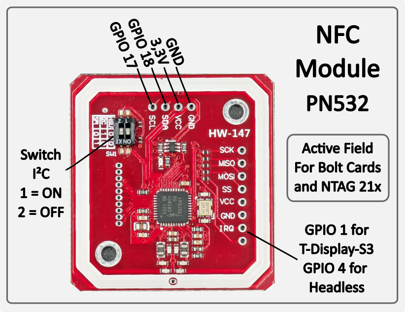
Bolt Cards & NTAG 21x (PN532, I²C 0x24) — Active NFC reader: the PN532 generates its own magnetic field and reads cards placed on it. Supports pre-programmed Bolt Cards for contactless Lightning payment. Also reads passive NFC tags of type NTAG 213, 215 and 216 — e.g. for LNURL-based payment tags. Works with all major Lightning wallets and PoS systems. No configuration required — the module is auto-detected on the I²C bus at startup.
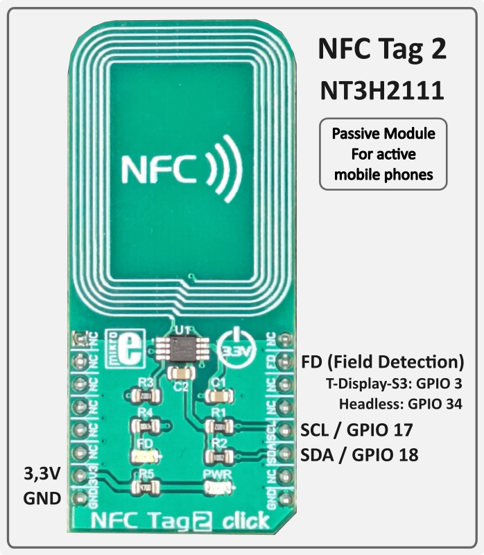
Mobile Phones (NFC Tag 2 / NT3H2111, I²C 0x55) — Passive NFC tag: unlike the PN532, the NT3H2111 generates no field of its own. It is a true NTAG chip that delivers the LNURL autonomously as soon as the active field of an approaching mobile phone is detected. The ZapBox writes the current LNURL to the chip via I²C — the ESP32 is not involved during the tap. Compatible with Android NFC Tools and wallets that support LNURL via NFC (e.g. Phoenix). No configuration required — auto-detected at startup.
Both modules operate independently and in parallel. If a module is not connected, it is simply skipped — normal operation is not affected.
The ZapBox features a hierarchical error detection system with automatic diagnostics. Error states show distinct blink patterns on GPIO 21 and GPIO 2 (onboard LED):
| Priority | Error Type | LED Pattern | Description |
|---|---|---|---|
| 1 (Highest) | NO WIFI | 1 blink | WiFi network not connected → Wifi data correct? → WiFi signal too weak? |
| 2 | NO INTERNET | 2 blinks | Internet connectivity lost → Internet accessible? |
| 3 | NO SERVER | 3 blinks | LNbits server unreachable -> Server hardware down? -> Device string correct? |
| 4 (Lowest) | NO WEBSOCKET | 4 blinks | WebSocket protocol/handshake failure -> LNbits down? -> Device string correct? |
Note: Higher priority errors override lower priority error displays. Each error pattern has a 2 second pause between sequences. Use the serial terminal to monitor detailed error messages.
Note: The headless version (ESP32 Dev Module without display) does not have a visual Report page. Use the serial terminal to monitor all errors and status messages.
If a wallet scanning the QR code shows an error message, here's what it means:
"bitcoinswitch ... is disabled" → The Bitcoin Switch was actively disabled in LNbits
"No active bitcoinswitch connections" → The handshake between the wallet and ZapBox failed. -> Wait or restart the ZapBox to re-establish the connection.
Relay does not switch, but payment was successful → Wrong GPIO pin configured in LNbits?
If you tap an NFC Bolt Card or NTAG21x tag and the serial log shows:
[WARN][NFC] Bolt Card tap detected – NFC is not supported by the active extension (bitcoinswitch).
[WARN][NFC] To use NFC / Bolt Cards, switch to zapbox_extension (apiPath = "zapbox").
This means the device is configured with the bitcoinswitch_extension, which does not have an NFC endpoint (/api/v1/nfc/). NFC payments are only supported by the zapbox_extension.
Solution:
This is not a hardware problem – the NFC reader works fine. It’s purely a server-side configuration issue.
{"detail":"LNURLW callback error: Payment failed - "}
The sending wallet and the receiving wallet in LNbits are the same. The Bolt Card wallet and the receiving wallet must be different wallets in LNbits.
Some ESP32s must first be put into mode before flashing or transferring data. Otherwise, they will refuse to transfer. Try these:
Source: esp32.implrust.com
Main page: https://zapbox.space
Web installer – T-Display-S3: https://installer.zapbox.space
Web installer – Headless (esp32dev): https://installer.zapbox.space/headless/
Further documentation: https://ereignishorizont.xyz/en/zapbox-en/
GitHub – ZapBox: https://github.com/AxelHamburch/ZapBox
GitHub – zapbox_extension: https://github.com/AxelHamburch/zapbox_extension
Extension manifest source: https://installer.zapbox.space/extensions.json
LNbits: https://lnbits.com/
GitHub – bitcoinswitch_extension: https://github.com/lnbits/bitcoinswitch_extension
bitcoinSwitch web installer: https://bitcoinswitch.lnbits.com/
MakerBits Telegram Gruppe: https://t.me/makerbits